-
Видеонаблюдение
- Готовые комплекты видеонаблюдения
- HD SDI Системы видео наблюдения
- IP Системы видео наблюдения
- AHD Системы видео наблюдения
- TVI Системы видео наблюдения
- CVI Системы видео наблюдения
- Видеонаблюдение для транспорта
- Устройства хранения данных
- Портативные видео камеры
- Тепловизор, Термальные прицелы
- корпуса для видеорегистраторов
- Видео камеры
- Объективы для видео камер
- Кронштейны и корпусы (домики)
- Мониторы для систем видео наблюдения
- Оборудование для изображения – обработка, передача, конверторы
- Блоки питания, UPS
- Поворотные механизмы для видео камер
- IR + LED прожекторы
- Кабельная продукция
- Защита от перенапряжения
- Силикагель
- Микрофоны
- Коннекторы
- Азбука видеонаблюдения
- Архив
- Охранная сигнализация
- Контроль доступа
- Переговорные системы
- Пожарные системы
- Видеодомофоны и домофоны
- Автоматика для ворот и шлагбаумы
- Сетевое оборудование
- Системы оповещения
- Коммутационные и серверные шкафы, аксессуары
- Инструменты
- Кабели, укрыватели, трубы и принадлежности
- Аккумуляторы, трансформаторы, блоки питания
- HDMI
- Аксессуары для караванов и кемперов
- Электромонтаж
- Солнечная энергия
- Ветровая энергия
- Контакты
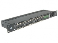
TRV-8/16PRC-RACK - PROGRAMMABLE VIDEO SPLITTER
The RV-8/16PRC-RACK video splitter allows to distribute, amplify and correction of the video signal from 8 inputs to 16 outputs according to configuration set by the user.
The RV-8/16PRC-RACK works default as eight independent video splitters 1/2. The configuration of the device can be change by simple digital interface, and current settings and options are displayed on LCD. To change the operation settings of the RV-8/16PRC-RACK device choose one of the options from the menu and change its parameter according to the user requirement.
There are many ways of outputs and inputs configuration. Total amount of possible settings is equal: 128. Please see below, to read the detailed information about the outputs and inputs configuration.
The RV-8/16PRC-RACK video splitter has a gain control function for each input from -3dB to +6dB. It enables signal level control and allows to avoid overdrive (by negative amplification on the decibel scale) or to amplify the too low level signal (by positive amplification on the decibel scale).
The next feature of the device is the correction of the transmitted video signal. It enables the cable length frequency compensation. It saves good image parameters even then were used long video transmission cables.
SPECIFICATIONS
|
Number of inputs: |
8 BNC |
|
Number of outputs: |
16 BNC |
|
Bandwidth: |
0 to 40 MHz (without correction) |
|
Inputs impedance: |
75Ω |
|
Outputs impedance: |
75Ω |
|
Power: |
230V AC / 30mA |
|
Gain: |
-3dB to +6dB (with step 0.5dB) |
|
The cable length correction: |
0 to 600m (with step 40m) |
|
Case type: |
1RU (19") |
|
Dimensions: |
44 x 490 x 120mm |
|
Weight: |
1.5kg |
Front panel view:

Top view:

The programming options are simple and intuitive, any informations are displayed on the LCD:
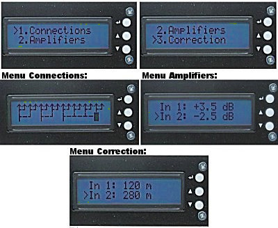
Configuration of the splitter
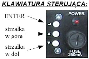
The configuration menu of the splitter is displayed on two lines LCD. After switch the power on, the name of the device is displayed and after a while the main menu options are enabled. There are three main menu options (1.Connections, 2.Amplifiers, 3.Correction). The UP/DOWN arrow symbol keys allow to change the menu options. To enter the submenu options or to change the parameters, press the ENTER symbol key.
Inputs/outputs connections (1.Connections)
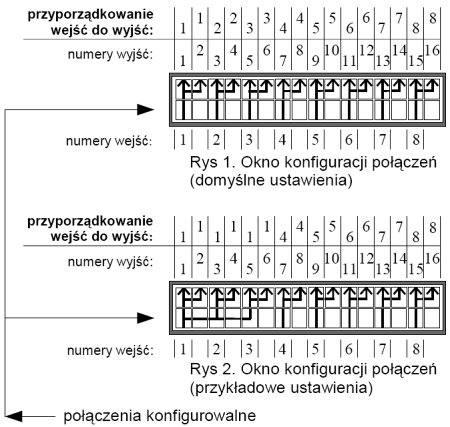
After enter the Connections submenu, the user can configurate the multiplexer, which connects the device inputs to the outputs. The connections are displayed as a graphic (see the Pic. 1 and Pic. 2) as follows:
- the top line of the display means 16 signal outputs (8 pairs),
- the bottom line of the display means the inputs of the splitter and can be modified by the user.
Menu adjustment from the splitter front panel:
- the UP arrow symbol key - enables switching among splitter inputs,
- the DOWN arrow symbol key - enables change the state of specific input of the switcher,
- the ENTER symbol key - confirms the changes and exits to the upper menu.
The configuration changes of the inputs allow to select between the signal from the current video input and the signal from the last connected input.
The picture below shows 2 examples from 128 all possible settings:
- default setting - each pair of output is connected to the corresponded input (Pic. 1),
- example of setting - the outputs from 1 to 6 are connected to the input 1, the outputs from 7 to 16 are connected as default (Pic. 2).
The input signal amplification (2.Amplifiers)
The RV-8/16PRC-RACK allows to control the level of the output signal (Pic. 3), it means the amplification of the signal (in case of low amplitude of the signal) or the attenuation of the signal (when the level of the signal exceeds the allowed value). The level of the signal can be adjust from -3dB to +6dB, with step 0.5dB. The 0dB value means that the level of the output signal is the same as the level of the input signal.
To configure the amplification for the specific input, enter to the Aplifiers submenu and choose the specific input using the UP/DOWN arrow symbol keys. To change the amplification value press the ENTER key. When the key is pressed the applification value increases. To set the negative values (attenuation), press the ENTER key until negative values will be displayed. The configuration settings are saved after exit the Amplifiers menu. To exit the Amplifiers menu choose the position "Save & Return" by the UP/DOWN arrow symbol keys and confirm by pressing the ENTER symbol key.
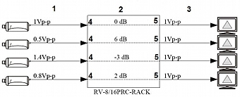
Pic. 3. Example of the connected cameras with the wrong levels of the video signals
The frequency compensation of the signal cable length (3.Correction)
The RV-8/16PRC-RACK splitter has built-in the frequency compensation module, which prevents the distortions of the video signals, when the signals are transmitted via the long distance cables (Pic. 4). The configuration of the device in this case, enables to set the length of the cable connected to the specific input from 0 to 600 meters, with step 40 meters. The frequency compansation means the frequency correction of the signal and the compensation of the signal level drop of the conductor resistance.
To set the correction for specific input, enter to the Correction submenu, and choose the specific input using the UP/DOWN arrow symbol keys. To change the value of the correction press the ENTER symbol key. When the key is pressed the distance value increases. To set the lower values, press the ENTER key until the "0" values will be displayed, and so on to the right one. The configuration settings are saved after exit the Correction menu. To exit the Correction menu choose the position "Save & Return" by the UP/DOWN arrow symbol keys and confirm by pressing the ENTER symbol key.

Pic 4. Example of the connected cameras with the long distance cables
The correction of the signal is very important for the long distance video signal transmission. The attenuation of the cable causes lower quality and sharpness of the transmitted image. The only possible solution is the active compensation method adjusted to the specific length of the cable. The RV-8/16PRC-RACK device enables clear and sharp image transmission up to 600m distance, and the difference between the transmitted and the source image is invisible in practise.
