-
Видеонаблюдение
- Готовые комплекты видеонаблюдения
- HD SDI Системы видео наблюдения
- IP Системы видео наблюдения
- AHD Системы видео наблюдения
- TVI Системы видео наблюдения
- CVI Системы видео наблюдения
- Видеонаблюдение для транспорта
- Устройства хранения данных
- Портативные видео камеры
- Тепловизор, Термальные прицелы
- корпуса для видеорегистраторов
- Видео камеры
- Объективы для видео камер
- Кронштейны и корпусы (домики)
- Мониторы для систем видео наблюдения
- Оборудование для изображения – обработка, передача, конверторы
- Блоки питания, UPS
- Поворотные механизмы для видео камер
- IR + LED прожекторы
- Кабельная продукция
- Защита от перенапряжения
- Силикагель
- Микрофоны
- Коннекторы
- Азбука видеонаблюдения
- Архив
- Охранная сигнализация
- Контроль доступа
- Переговорные системы
- Пожарные системы
- Видеодомофоны и домофоны
- Автоматика для ворот и шлагбаумы
- Сетевое оборудование
- Системы оповещения
- Коммутационные и серверные шкафы, аксессуары
- Инструменты
- Кабели, укрыватели, трубы и принадлежности
- Аккумуляторы, трансформаторы, блоки питания
- HDMI
- Аксессуары для караванов и кемперов
- Электромонтаж
- Солнечная энергия
- Ветровая энергия
- Контакты
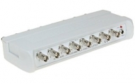
TRV-8/16 - PRPROGRAMMABLE VIDEO SPLITTER
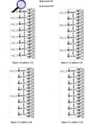
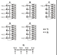
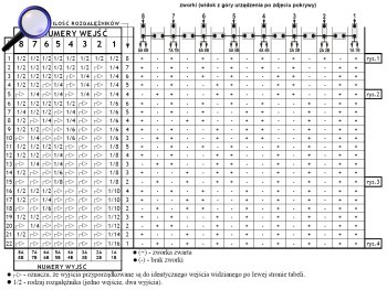
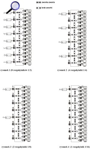
The RV-8/16PR video splitter allows to distribute video signal from eight inputs to sixteen outputs according to configuration set by the user. The RV-8/16PR has the default array set as eight independent video splitters 1/2 (Fig. 1). It is easy to re-program the array using jumpers located on the front panel. There are 22 combinations available. The example four ones are given in the figures. When programming, the table of possible combinations should be employed. The vertical jumpers activate respective inputs and the horizontal ones - connect respective outputs. The splitter is designed for continuous indoor operation. The RV-8/16PR works with any CCTV cameras. The LED informs about power on. Splitters can be connected in series.
Example: There is a need for 4 video splitters 1/4 (one input, four outputs). On the left side of the table one can find the line containing required devices: 4 x 1/4 (position LP5). The fields with "1/4" forks show inputs (the upper part of the table) and assigned to them outputs (the lower part of the table). The fields with arrows show which outputs are consigned to the same input seen on the left. In the right part of the table the columns are assigned to the respective jumpers. In the same line there is given information about which jumpers have to be put (+), and which are unused (-). The example is shown in Fig. 2.
SPECIFICATIONS
|
Number of inputs: |
8 x BNC female |
|
Number of outputs: |
16 x BNC female |
|
Video bandwidth: |
0 - 40 MHz (-3 dB) |
|
Inputs impedance: |
75 Ω |
|
Outputs impedance: |
75 Ω |
|
Power: |
DC 12V / 100mA |
|
Gain: |
0dB |
|
Dimensions: |
222x36x110 mm |
|
Weight: |
350g |
The splitter configuration table:
Click on the table to enlarge
4 examples of splitter configuration:
Front view:

Rear view:

Inside view (from the top):
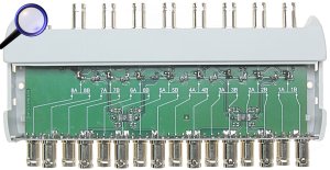
The way of remove the cover:

