-
Videonovērošana
- Gatavie videonovērošanas komplekti
- HD SDI
- IP Sistēmas
- AHD Videonovērošana
- TVI Videonovērošana
- CVI Videonovērošana
- Transporta videonovērošana
- Datu glabāšanas iekārtas
- Portatīvas video kameras
- Thermal, Termālie tēmēkļi
- DVR kārbas
- Videokameras
- Objektīvi
- Kronšteini un apvalki
- Monitori
- Ierīces video attēlošanai - video signāla apstrāde un pārsūtīšana
- Barošanas bloki, UPS
- Grozāmie mehānismi
- IR + LED prožektori
- Kabelis
- Zibens aizsardzība
- Silikagels
- Mikrofoni
- Konektori
- ĀBECE
- arhivs
- Apsardzes signalizācija
- Kontroles sistēmas
- Sarunu sistēmas
- Ugunsdzēsības sistēmas
- Audio un Video domofoni
- Automātika vārtiem un barjeras
- Tīkla iekārtas
- Apskaņošanas sistēmas
- Kommutācijas un Serveru skapji, piederumi
- Instrumenti
- Kabeļi,aizsegi,caurules un piederumi
- Barošanas bloki,transformatori un akumulātori
- HDMI
- Piekabju un kemperu piederumi
- Elektromontāža
- Saules enerģija
- Vēja enerģija
- Kontakti
TRV-8/16 - PRPROGRAMMABLE VIDEO SPLITTER
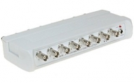
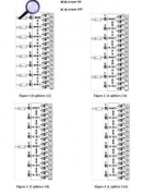
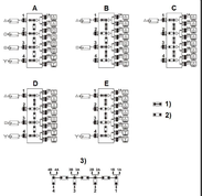
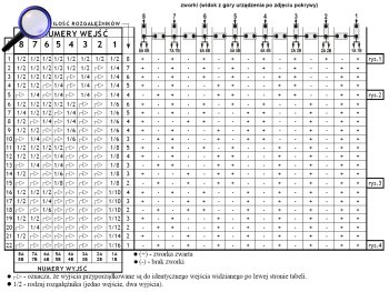
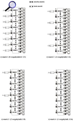
The RV-8/16PR video splitter allows to distribute video signal from eight inputs to sixteen outputs according to configuration set by the user. The RV-8/16PR has the default array set as eight independent video splitters 1/2 (Fig. 1). It is easy to re-program the array using jumpers located on the front panel. There are 22 combinations available. The example four ones are given in the figures. When programming, the table of possible combinations should be employed. The vertical jumpers activate respective inputs and the horizontal ones - connect respective outputs. The splitter is designed for continuous indoor operation. The RV-8/16PR works with any CCTV cameras. The LED informs about power on. Splitters can be connected in series.
Example: There is a need for 4 video splitters 1/4 (one input, four outputs). On the left side of the table one can find the line containing required devices: 4 x 1/4 (position LP5). The fields with "1/4" forks show inputs (the upper part of the table) and assigned to them outputs (the lower part of the table). The fields with arrows show which outputs are consigned to the same input seen on the left. In the right part of the table the columns are assigned to the respective jumpers. In the same line there is given information about which jumpers have to be put (+), and which are unused (-). The example is shown in Fig. 2.
SPECIFICATIONS
|
Number of inputs: |
8 x BNC female |
|
Number of outputs: |
16 x BNC female |
|
Video bandwidth: |
0 - 40 MHz (-3 dB) |
|
Inputs impedance: |
75 Ω |
|
Outputs impedance: |
75 Ω |
|
Power: |
DC 12V / 100mA |
|
Gain: |
0dB |
|
Dimensions: |
222x36x110 mm |
|
Weight: |
350g |
The splitter configuration table:
Click on the table to enlarge
4 examples of splitter configuration:
Front view:

Rear view:

Inside view (from the top):
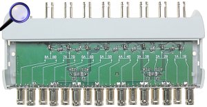
The way of remove the cover:

